I’m kinda fascinated by USB-C. It has it’s issues but I can’t help but love this magical omni-cable that holds the promise of hundreds of watts of power and gigagbits per second of bandwidth. It’s reversible, you can negotiate the supply voltage (PD), send power in either direction, pipe PCIe or DisplayPort and talk to the cable itself.
USB PD lets you ask for different supply voltages, roughly you can ask for, the voltage is fixed and the amps and power column are the max you’re allowed to pull for that profile.
| Power | Voltage | Current |
|---|---|---|
| 15W | 5 V | 3A |
| 27W | 9 V | 3A |
| 45W | 15 V | 3A |
| 60W | 20 V | 3A |
| 100W* | 20V | 5A |
100W mode requires the cable to have a special E-marker that reports that it supports the extra current. Later revision of the standard have added higher voltages (EPR) and fully adjustable supply voltage (PPS) but I won’t go into that here.
I’m going to be using a cheap 60W and 100W USB modules from AliExpress. These boards take 24V input and have a DC-DC converter and IC onboard to negotiate and generate the requested voltage. So the basic idea is to connect a bunch of these connect to a 24V power supply.
I had a look online to see what the maximum charging rate of some common devices are:
| Device | Max Charge Rate |
|---|---|
| Framework | 180W |
| Some Macbooks | 140W |
| Most Laptops | 100W* |
| Beefy Battery | 60W |
| Steam Deck | 40W |
| iPhone | 27W |
| Airpods | 5W |
I’ll be using 100W modules so let’s ignore anything above that say the most I could reasonable want to charge at once would be two phones, two wireless headphones, a portable battery, a laptop and a steamdeck. That sums to about 300W total. I’m going to go for 3 100W modules and 5 60W modules for a theoretical maximum draw of 600W but I don’t have enough devices to achieve that.
This project has been the subject of a ridiculous amount of scope creep. What follows is basically my notes on what I’ve done so far.
Case Design
After initially thinking I would do some kind of charging tray type design I eventually decided to model the PSU into a book-like form factor so that it can hide on the bookshelf in our living room, nestled between real books. The cables will then snake out of the back and emerge from between the books. This keeps the cables nicely separated and hides the extra cable length well. I’ll need to be careful about cooling though.
This is what I’ve come up with so far, it’s lasercut from 3mm ply (but I need to switch to 4mm because 3mm is a bit flimsy)
I’ve put a 240x240 pixel colour screen on the front to show metrics like total charge power, temperature and maybe daily energy use.
Electronics
Because I am taking this way too far, I wanted to do per port enable/disable and current monitoring. To implement this I’m designing a PCB with 5 channels where each channel consists of this schematic.
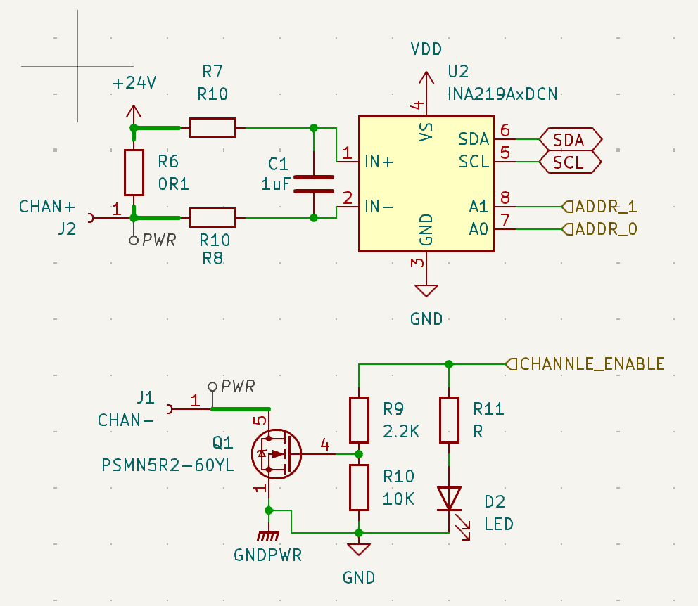
There’s an INA219 and a shunt resistor for current and voltage monitoring and a chunky MOSFET for enabling and disabling the channel.
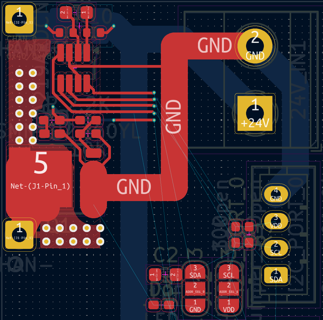
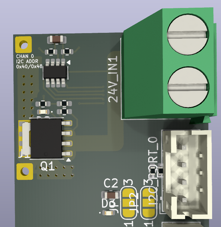
For now I’ve broken the functionality for one channel out into a test board that I’ve sent off to JLCPB for manufacturing with and to be populated with SMT components. This ended up costing about 50 dollars for 5 boards. In future I want to have a go at doing the component placement and reflow myself.
Loading model...
And here’s the board as it arrived in the post.
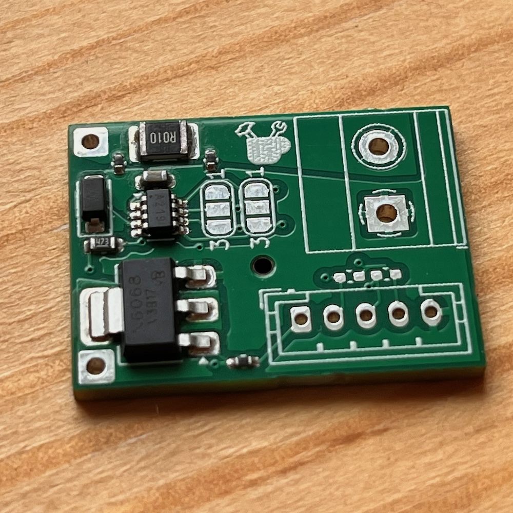
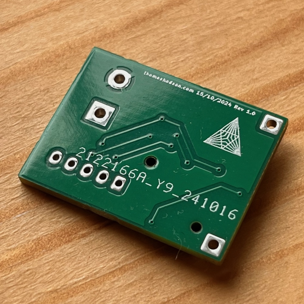
At this point I realised I had ordered 2.54mm connectors instead of 2mm pitch connectors which I had swapped in at the last minute to reclaim some board space.
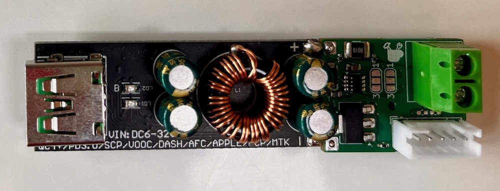
When those eventually arrived I soldered it up and attached it to the downstream USB-C power board that it will be monitoring. 24V goes into the terminal block on the right. I2C for current monitoring and a logic level enable pin go into the 5 pin connector in the bottom right.
I haven’t had a chance to properly test this yet. Particularly, I’m anxious to find out how much power the MOSFET dissipates when its gate is driven at 3.3V and the downstream load is pulling 5A. If it’s too much I’ll stick in a level shifter and hope that driving it to 5V will be enough!
Software
In other posts I’ve described how I made this simulator the test out possible GUIs for this thing. This is the micropython code running in a slightly tweaked version of the micropython interpreter compiled to webassembly.

TODO: Add some knobs to the simulator so you can test different conditions such as overcurrent, overtemp, sleep, nightmode etc.
